Some manufacturers provide their measurement equipment as a “one size fits all” or “take it or leave it” approach and may require mill modifications to “fit” their equipment. We feel this is an unnecessary approach and disliked by many customers. There are many forms of equipment mounting schemes to work within the constraints of the existing line.
We offer customized frames and mounting schemes to fit within the existing mill and process lines many times re-using the existing track assemblies. We offer traditional c-frames for centerline measurement, scanning frames with drive systems, Internal scanning options with or without drives to bring the unit offline but the sensors scan internally on linear slide assemblies. We offer mill mount/line mount systems with the sensors mounted with covers as required. We also offer “O” frame assemblies and inverted frames to fit within line openings.
Global Gauge Corporation has produced two basic types of Scanning Gauges, with some variations within each type: A gauge with a scanning C-frame or a gauge with scanning internal sensors.
Scanning C-frame Type:
In this approach, the sensors are fixed inside the C-frame, and the C-frame assembly traverses back-and-forth to measure the width of the strip. Two common variations include a base-mounted track (C-frame sits on track) or an overhead track (hanging C-frame).
Scanning Sensor Type:
In this approach, the sensors are fixed on belt-driven plates, which are mounted to bearings on linear slide assemblies inside the frame. During scanning, the sensors traverse back and forth on the linear bearings. Two common variations include a fixed O-frame or a retractable C-Frame on a base-mounted track.
Please note that the few variations listed above do not indicate a limitation on our offering. Mostly it is a list of what customers have requested up to this point in time. For example, we could also produce hydraulically or pneumatically driven C-frames, or we could produce Scanning Sensor based units with Retractable C-frames that are also suspended from an overhanging track, etc. There are many, many combinations that could be created, based on the customer’s needs.
A general description of some units is provided below, along with some basic benefits and disadvantages of each.
Scanning C-frame with Base Mounted Track
This is the most basic (and most common) scanning C-frame design. The unit consists of a C-frame with a throat depth that is adequate to scan the entire width of the material plus any additional mill items that might impede the full scanning. Oftentimes the throat depth of the scanning C-frame is approximately twice the depth of the centerline C-frame. Typically, the C-frame includes wheels and a drive system, and the entire assembly rides on a static track. The most common drive system is a motor/gearbox/sprocket arrangement.
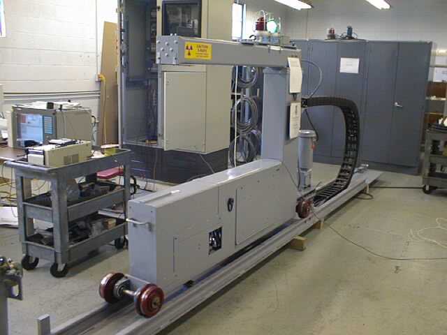
Benefits: This is one of the most basic and common types of scanning C-frames. Many customers are comfortable with this approach. The system is simple to understand and easy to maintain.
Scanning C-frame with Overhead Track
In this variation, the C-frame is suspended from an overhead track. A photo of a Scanning C-frame with an Overhead Track is shown in the photo below. In this case, a gear rack was mounted to the underside of the overhead track, and a motor/gearbox/gear arrangement was used as the traversing mechanism. Also, note that this installation required that the bottom portion of the C-frame (which supported the generator) be carefully designed, so that some mill equipment at the rear of the track was not impacted.
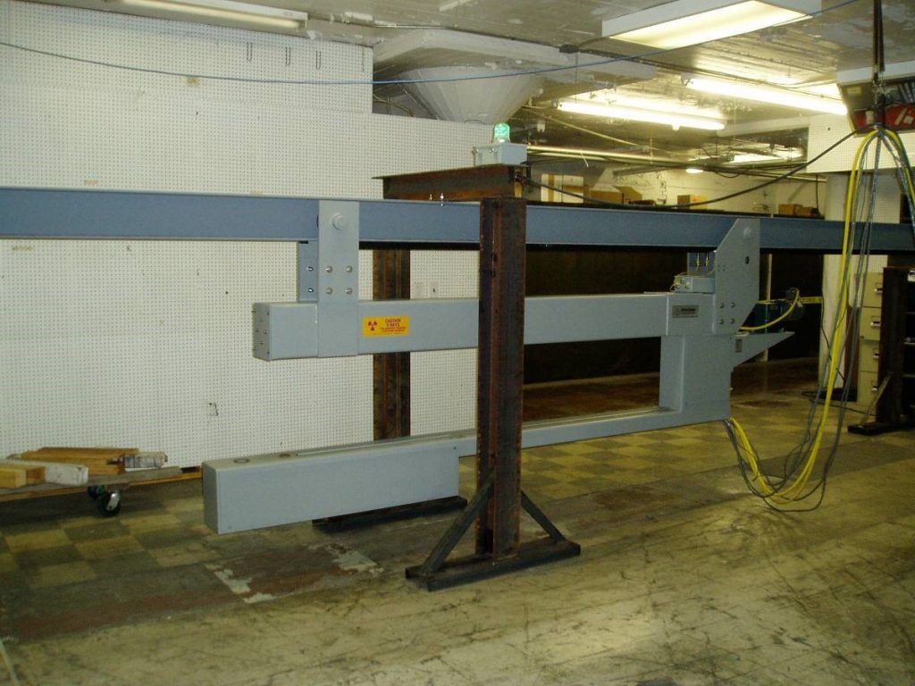
Benefits: An overhung C-frame is typically used when there are mill obstructions which prohibit the installation of a track, or when the mill dirt/residue would make a base mounted track a poor choice. Overhung track assemblies are reported to require less maintenance on the wheels due to less dirt collecting on the rolling surfaces.
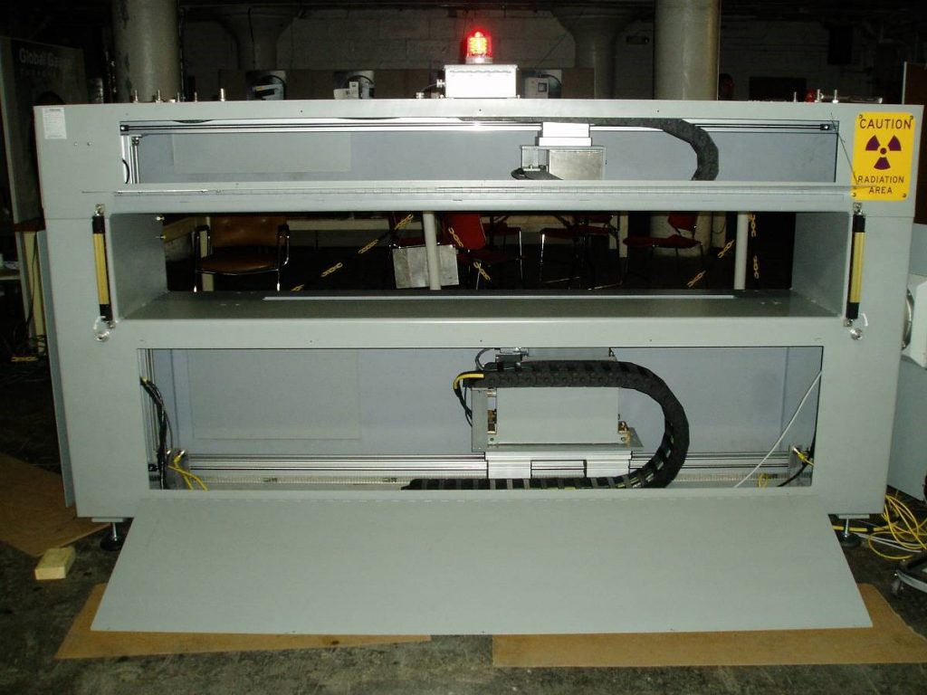
Scanning Sensors with Fixed O-frame
In this approach, the sensors are mounted to belt driven linear slides, and the linear slide assemblies are mounted inside a fixed O-frame. The O-frame is then permanently mounted within the mill or at the exit of the mill. This approach can also be used as an off-line profilometer. The upper and lower linear slides are mechanically linked with a vertical drive shaft. When the vertical drive shaft is rotated one direction or the other, the upper and lower sensors reciprocate with little backlash, such that the beam alignment is maintained with great precision.
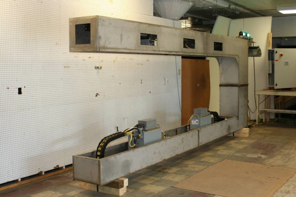
Scanning Sensors with Retractable C-frame (on Base Mounted Track)
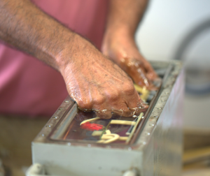
The photo below shows a Stainless-Steel C-frame during construction which included a variation of the scanning sensors. In this case the design was enhanced to permit two sets of sensors on separate slides for a hot strip mill. The slides are controlled by separate drive systems to permit independent scanning and/or positioning. (Of course, the scanning control system includes the proper interlocks to keep the sensors from crashing into each other.) The approach of two sets of sensors permits even more scan data to be collected.
At Global Gauge, our goal is to work with the end user to provide high quality equipment without major mill modifications which saves time and a lot of money.